SCI

SCI Thermal Shock Chambers — Landing Page

Environmental Test Chambers / Thermal Shock Chamber Family
SCI THERMAL SHOCK CHAMBER FAMILY

One interface for two-zone and three-zone shock systems.

Choose the shock architecture first, then compare the approved 64–1,000 L two-zone basket models, specimen fit, utilities and real engineering evidence. Three-zone static chambers are integrated in the same family interface without borrowing two-zone specifications.

Two-zone basket familyThree-zone static familyFive approved basket modelsOriginal shock record
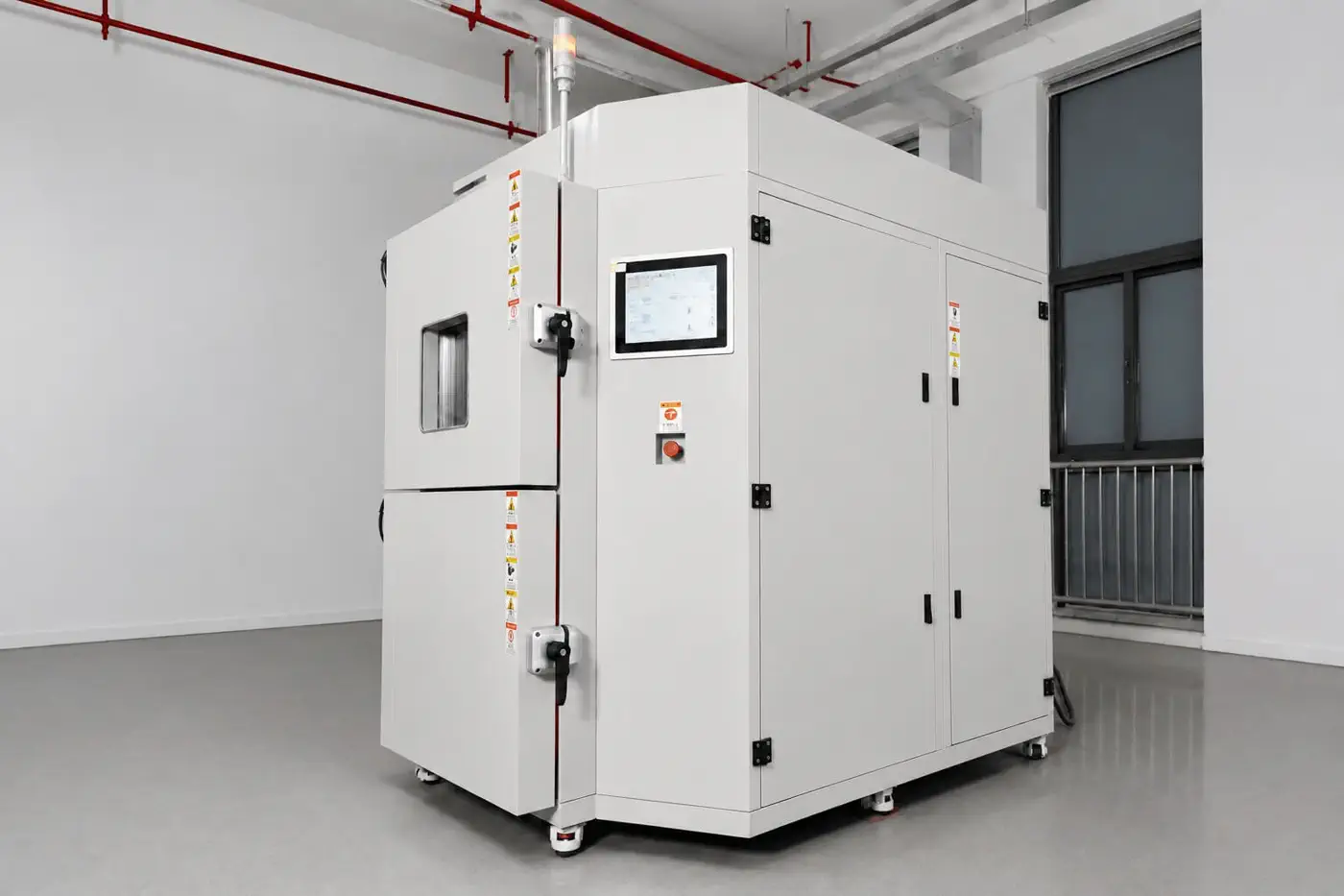
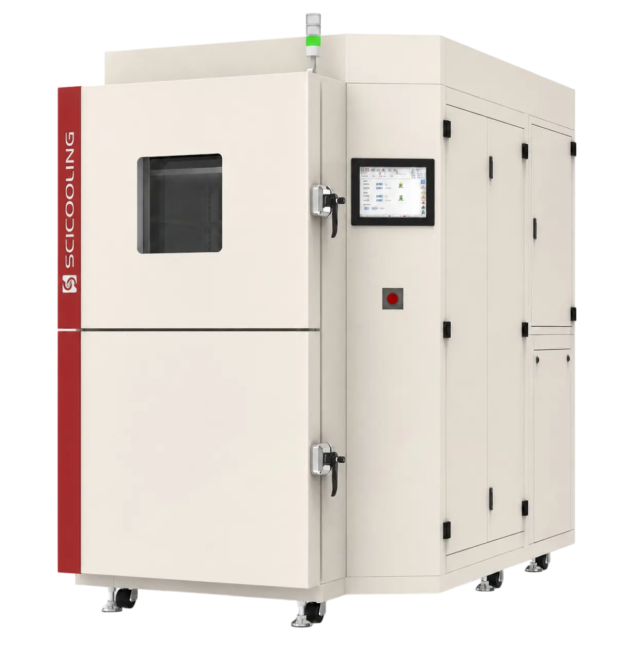
SCI thermal shock chamber family
SCI THERMAL SHOCK FAMILY · REAL CHAMBER VIEWFinal architecture, model and options follow the approved project specification.
64–1,000 LApproved two-zone volume rangeFive published model classes
2Core shock architecturesBasket transfer or static three-zone
5Published model classesFrom compact to large workspace
5–60 kg150 → −40°C load referenceModel and acceptance basis govern
03.1 · PRODUCT FAMILY CONFIGURATOR

Two-Zone Basket → Three-Zone Static

Choose the thermal-shock architecture first. The approved two-zone basket table below contains five published models from 64 to 1,000 L; three-zone chambers share this page structure but retain their own project-specific specification boundary.

SCI two-zone vertical basket thermal shock chamber
MOVING SPECIMEN · TWO CONDITIONED ZONES

Two-zone basket thermal shock

One specimen basket transfers between independently prepared hot and cold zones. Select this architecture when fast environmental exchange around the same loaded fixture is the required method.

Specimen handlingOne basket moves between hot and cold zones.
Published model dataFive approved classes: 64, 125, 300, 512 and 1,000 L.
Selection driverWorkspace, rack load, specimen mass and recovery basis.
Interface optionsVertical or horizontal basket architecture by project.
Specification boundary: the table below applies only to the supplied two-zone basket family data.
Three-zone data remains separate. The architecture is integrated here, but no two-zone dimensions, power or load values are reused for the three-zone chamber. Add its approved model table when the corresponding specification is supplied.
APPROVED SOURCE TABLE · 5 MODELS

Two-Zone Basket Model Configurator

Temperature range for the supplied family: cold chamber −75 to +150°C; hot chamber +60 to +180°C. Dimensions are shown as W × H × D.

MID-SIZESCI two-zone basket thermal shock chamber
MID-SIZE · TWO-ZONE BASKETCTS-TC7025C-W

300 L Two-Zone Basket Chamber

Approved reference data from the supplied model table. Final selection must still be checked against the specimen, fixture, mass, recovery basis, utilities and destination power supply.

WORKSPACE · W × H × D650 × 710 × 650 mm
EXTERIOR · W × H × D2000 × 2340 × 2150 mm
OBSERVATION WINDOW · W × H350 × 300 mm
RACK LOAD / PRODUCT WEIGHT20 kg/layer · 1600 kg
PRODUCT CLASSTwo-zone basket family
SHOCK METHODMoving basket · hot/cold zones
CHAMBER TEMPERATURE RANGECold −75 to +150°C
Hot +60 to +180°C
LOAD REFERENCE12 kg @ 150→−55°C
30 kg @ 150→−40°C
SELECTION CHECKVerify the specimen and fixture fit within the 300 L workspace with airflow and handling clearance.
The product image represents the two-zone basket family. The selected row governs the published dimensions and utilities; the approved project drawing governs the final machine.
CONCEPT · PUT YOUR SAMPLE INSIDE

Interactive sample placement inside the basket

STATIC BASKET VECTOR
STAINLESS-STEEL BASKET300 L · 650 × 710 × 650 mm
SCI thermal shock chamber basket with selected test samplesSemi-realistic static vector showing the stainless-steel transfer basket, orange sealing gasket, wire mesh, guide rails and selected sample package.
Brushed stainless linerWire basket & guide railsSelected sample package
WORKSPACE FIT SCREEN

Battery modules

Preset sample package220 × 160 × 90 mm · 4 pcs
Estimated volume utilization—
Specimen / rack-load reference—
WORKSPACE FIT · PASSReserve clearance around every module and confirm fixture mass.
Concept screening only. Final selection requires actual sample dimensions, fixture mass, basket loading, cable routing, transfer clearance and the agreed recovery method.
Continue to C03 Site Planner →
03.2 · MODEL COMPARISON

Compare the approved two-zone family side by side.

Use the model code, workspace, observation window and basket-load class for the first selection. Project utilities and detailed engineering configuration are confirmed through enquiry.

MODELVOLUMECHAMBER RANGEWORKSPACE W × H × DWINDOW W × HRACK LOADPOSITIONING

Source: the supplied two-zone basket model table. Cold chamber range −75 to +150°C; hot chamber range +60 to +180°C. Confirm the specimen, fixture, recovery basis, project utilities and acceptance criteria through the approved quotation and technical specification.

02 · THERMAL TRANSFER ARCHITECTURE

The specimen stays in one basket. The environment changes around it.

A servo motor and screw-drive mechanism lifts or lowers the stainless-steel basket between the upper and lower chambers. Opposed covers seal the inactive zone, while each chamber maintains its own prepared condition.

ONE COMPLETE SHOCK CYCLE

Condition → transfer → recover → expose

Thermal-shock performance is not one speed number. Basket transfer, chamber recovery, specimen response and exposure time describe different parts of the cycle.

01
Precondition both zonesHot and cold chambers reach the programmed storage conditions.
02
Expose the specimenThe basket remains in the active zone for the defined dwell period.
03
Transfer verticallyThe drive moves the loaded basket while the sealing covers exchange positions.
04
Verify recoveryRecovery is judged at the agreed sensor position, load and acceptance method.
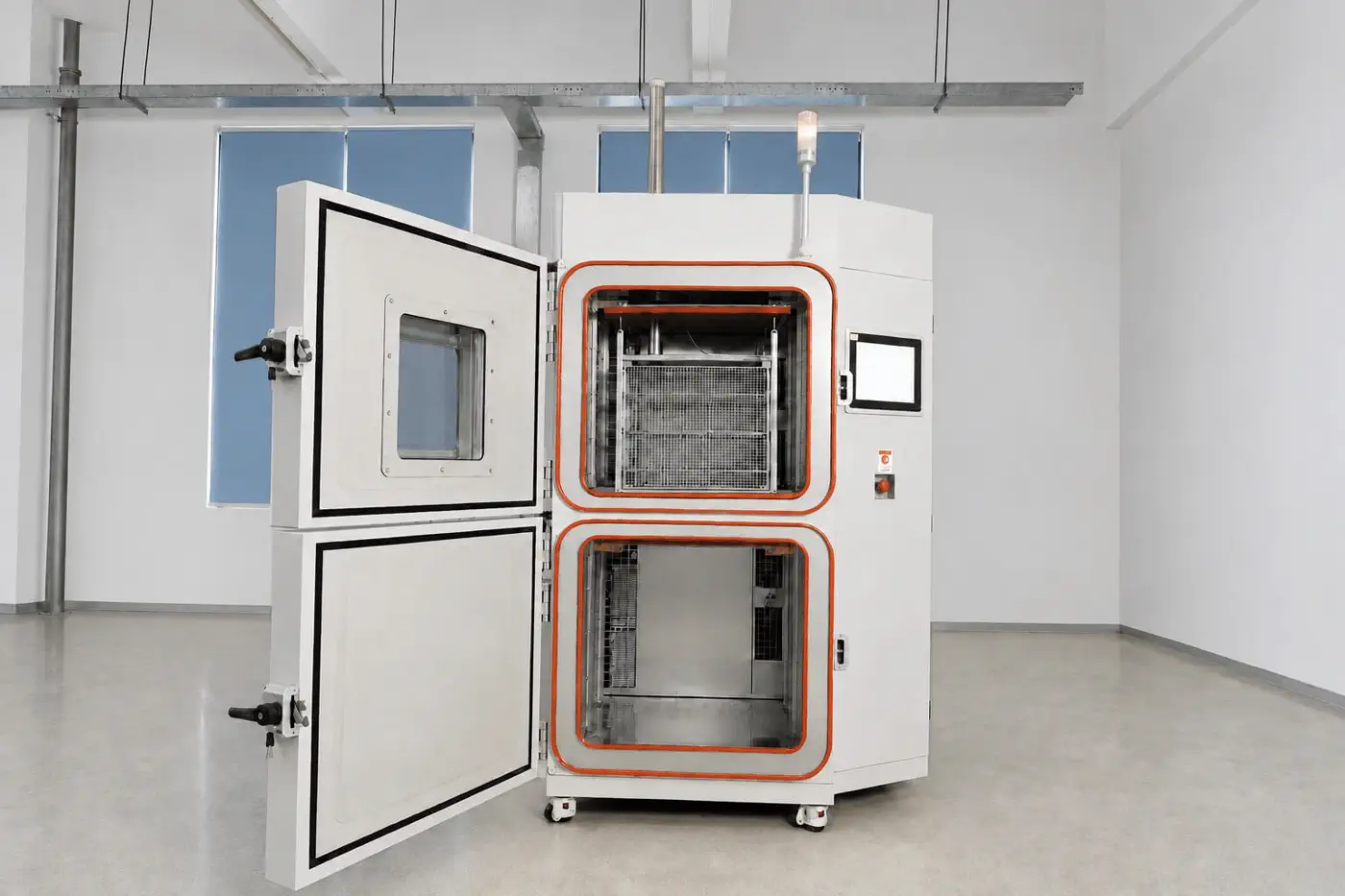
Interactive transfer viewSwitch the basket between conditioned zones.
UPPER · HOT ZONE
LOWER · COLD ZONE
SERVO + SCREW VERTICAL TRANSFER
Acceptance boundary: transfer time is the movement interval. Recovery time is the interval required for the specified chamber-air measurement to return within the agreed tolerance after transfer.
03 · CURATED REAL-EQUIPMENT DETAILS

Fewer photographs, each answering a different buyer question.

The gallery has been reduced to three distinct views per category. The selected image is shown once at full size; only the two alternative views appear beside it, avoiding repeated crops of the same component.

04 · SYSTEM ARCHITECTURE

Four systems must work as one cycle.

This section now uses a compact engineering summary instead of repeating photographs already shown in the real-equipment gallery.

01BASKET DRIVE

Servo-driven vertical transfer

Moving-basket sensing, opposed sealing covers and position monitoring support repeatable cycling.

02CHAMBER BODY

Welded SUS304 test spaces

Composite insulation, silicone seals, a heated observation window and controlled airflow protect both conditioned zones.

03THERMAL SYSTEM

Project-matched refrigeration

Refrigeration architecture is selected from the cold endpoint, specimen load, recovery basis and site utilities.

04CONTROL & SAFETY

PLC, sensing and interlocks

Overtemperature, pressure, phase, overload, airflow and emergency protections form coordinated layers.

Transfer verificationPosition, time and interlock logic
Zone verificationStorage, airflow and sealing
Recovery verificationEndpoint, load and sensor basis
Protection verificationAlarm, trip and specimen power
03.6 · PERFORMANCE EVIDENCE

Original thermal-shock evidence—and the boundary behind every number.

Start with the supplied source record, then separate basket transfer, chamber recovery, specimen response and exposure time. Final acceptance still follows the confirmed model, load, sensor position and method.

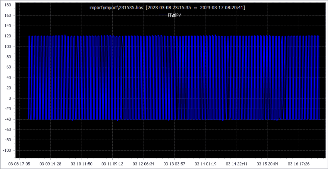
Original SP2595 thermal-shock recorder export
Original recorder export · S4 / SP2595No curve redrawing
THERMAL-SHOCK PLATFORM RECORD

100-cycle stored-condition endurance record

The full source window makes cycle continuity and repetition visible instead of reducing performance to a single marketing number.

PROJECTSP2595 · 2023
DISPLAYED WINDOW8–17 March 2023
HOT / COLD CONDITION+120°C / −40°C
RECORDED PROGRAM100 cycles

Evidence boundary: this source is platform evidence from a three-chamber stored-condition program; it is not presented as acceptance proof for every selected two-zone basket model. Confirm the exact model-specific record during engineering review.

Reference performance framework

Use this table to prepare the engineering conversation.

ITEMREFERENCEBOUNDARY
Basket transfer≤5 sFinal drive, basket mass and movement sequence govern.
Temperature recovery≤5 minHot/cold endpoints, exposure, load and outlet-air method must be agreed.
Temperature fluctuation≤1.0°CEmpty chamber, stabilized condition.
Temperature uniformity≤2.0°CEmpty chamber, stabilized condition.
Temperature deviation≤±2.0°CEmpty chamber, stabilized condition.
Control resolution0.1°CT-type thermocouple control input.

Four times buyers should separate

Collapsing these into one “speed” claim creates acceptance disputes.

Exposure timeHow long the specimen remains in the conditioned hot or cold zone.
Transfer timeMechanical movement from one chamber position to the other.
Recovery timeHow long the specified air measurement takes to return to tolerance.
Cycle timeTotal hot exposure, transfer, cold exposure and programmed transition logic.
Sample temperature is another measurement.The specimen core or surface may respond more slowly than chamber outlet air. Define the acceptance sensor and location before FAT.
05 · CONTROL, DATA & SAFETY

Program the cycle—and preserve the evidence trail.

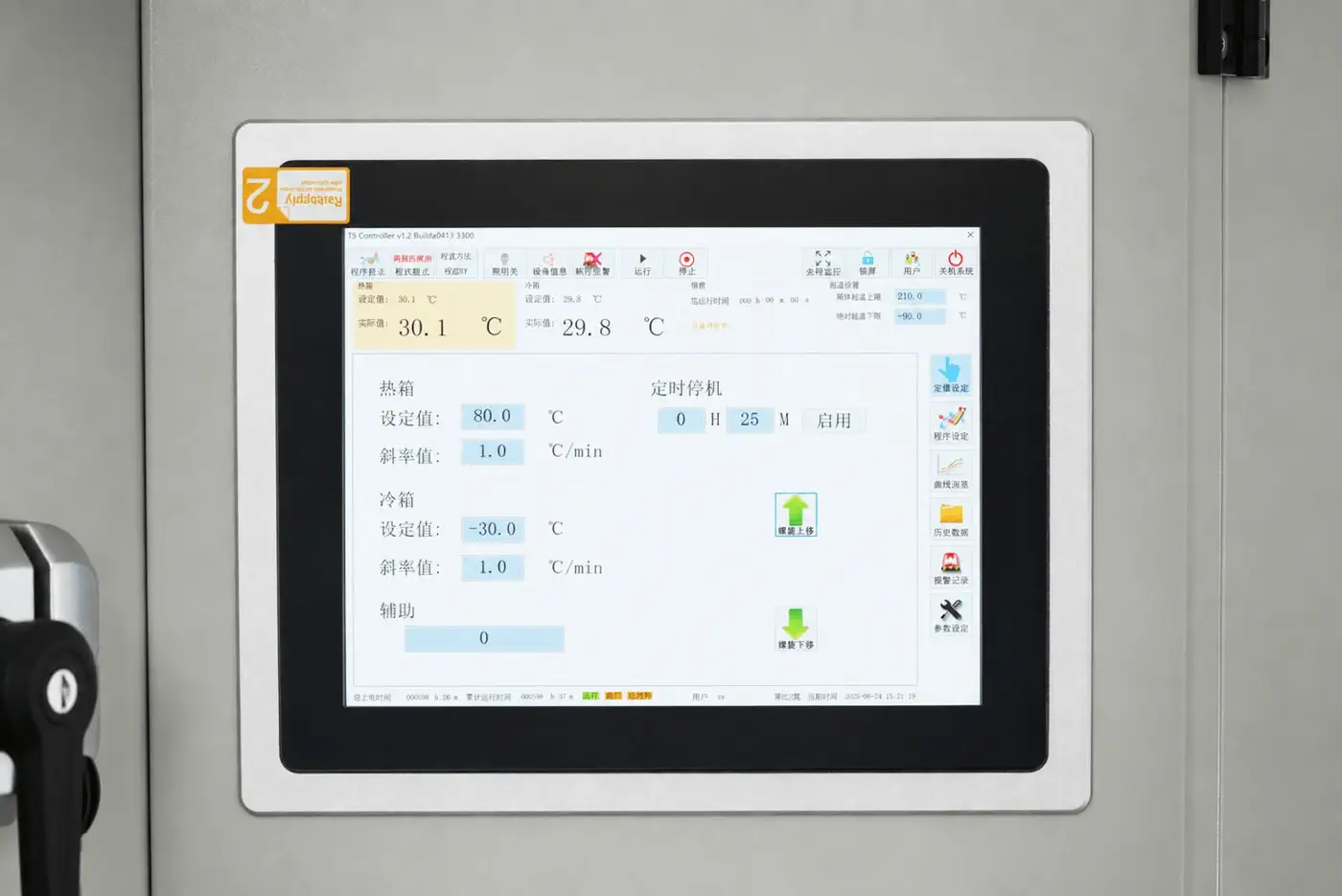
The controller coordinates zone setpoints, exposure time, basket position, cycles, defrost logic, alarms and data records. The photographed interface is from the supplied machine; final language and function set follow the selected controller release.

Real thermal shock chamber controller
Constant and program modesSet hot/cold targets, dwell periods, start zone, cycle count and related sequence parameters.
Position and status visibilityView basket location, zone setpoint/actual values, outputs, pressure and operating state.
Historical data and curvesRecord operating data, curves and alarms; export source data through the supported project interfaces.
Remote communicationsRS232/RS485 and Ethernet capability can support remote monitoring and service when configured.
Layered specimen protectionUser-set overtemperature, independent overtemperature, specimen-power interlock, emergency stop, pressure/temperature monitoring, compressor overload, phase and airflow/heater interlocks protect both chamber and sample.
Program capacity and the exact interface set are configuration items. Confirm the contractual release value rather than copying a generic family number into the order.
06 · CONFIGURATION INPUTS

A useful quotation starts with the test—not just the chamber name.

Send the parameters that materially affect basket size, refrigeration capacity, recovery, airflow, feedthroughs, utilities and the acceptance method.

01 · SPECIMEN

What moves in the basket?

  • Overall dimensions and quantity
  • Total mass and material heat capacity
  • Self-heating output during the test
  • Fixture, shelf and cable requirements
02 · TEST PROFILE

What defines one cycle?

  • Hot and cold exposure temperatures
  • Dwell time in each zone
  • Cycle count and starting zone
  • Applicable standard and sensor position
03 · SITE & OPTIONS

What must the installation support?

  • Power supply and incoming protection
  • Air- or water-cooled refrigeration
  • Dry air, drainage and feedthroughs
  • Handling route and service clearances
Basket fitSample + fixture + airflow clearance
Thermal loadMass, material and heat output
AcceptanceAir or specimen sensor + tolerance
UtilitiesPower, cooling, dry air and drainage
07 · REFERENCE STANDARDS

Manufacturing and test framework

IEC 60068-2-14 / GB/T 2423.22Change of temperature testing, including Test Na references.
IEC 60068-2-1 / GB/T 2423.1Cold testing framework.
IEC 60068-2-2 / GB/T 2423.2Dry-heat testing framework.
GJB 150.5ATemperature-shock test reference for applicable projects.
GB/T 5170.1 / 5170.2Environmental-test-equipment verification methods.
08 · BUYER FAQ

Questions that prevent the wrong selection

No. Transfer time measures basket movement; recovery time measures the chamber-air return to the agreed tolerance after movement.
Mass and heat capacity change the thermal load and can materially affect recovery and the specimen's actual response.
No. Basket size, load, dwell, cycle count, recovery basis, feedthroughs, utilities and condensation requirements also influence the system.
Dry-air control is considered when the test or specimen cannot tolerate condensation. Site dew point, pressure, flow and control scope must be confirmed.
Confirm the released model, basket/load, setpoints, dwell, transfer, recovery measurement, alarms, specimen power, data export and utility conditions.
03.9 · QUALITY BUILT INTO EVERY UNIT

223 documented line items — made visible.

The same inspection framework used on the temperature-and-humidity chamber page is applied here, connecting structure, transfer hardware, refrigeration, controls and release review in one traceable process.

CHECKPOINT DISTRIBUTION

Four disciplines. One traceable release record.

223DOCUMENTED LINE ITEMS
Electrical & control58
Structure & appearance55
Refrigeration48
Commissioning & release62
ISSUE CLASSIFICATION ACROSS THE RECORDA / B / C + open lines
A · 103B · 93C · 20Open / other · 7
Thermal shock chamber structure inspection view
Structure & door sealing
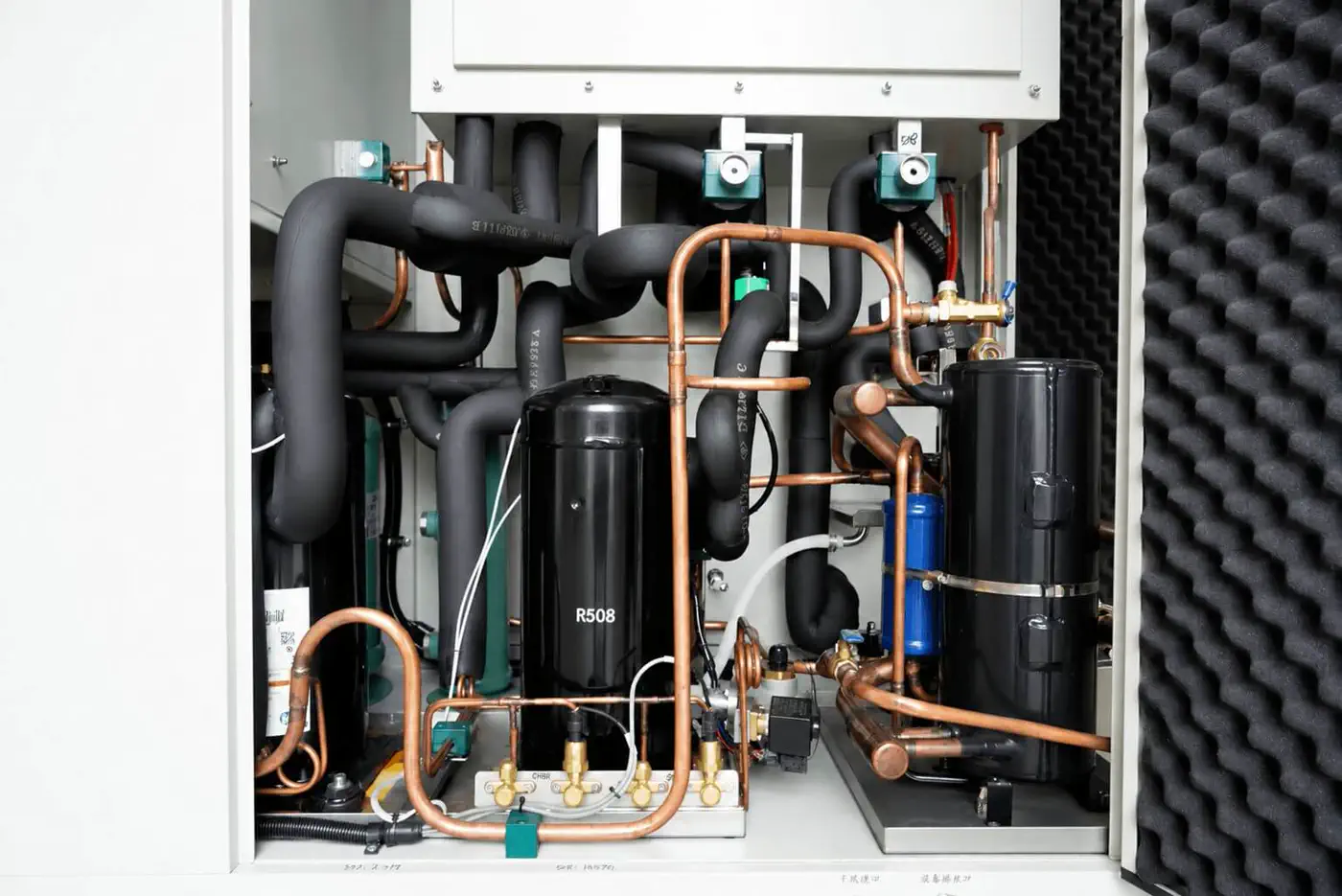
Thermal shock refrigeration inspection view
Refrigeration workmanship
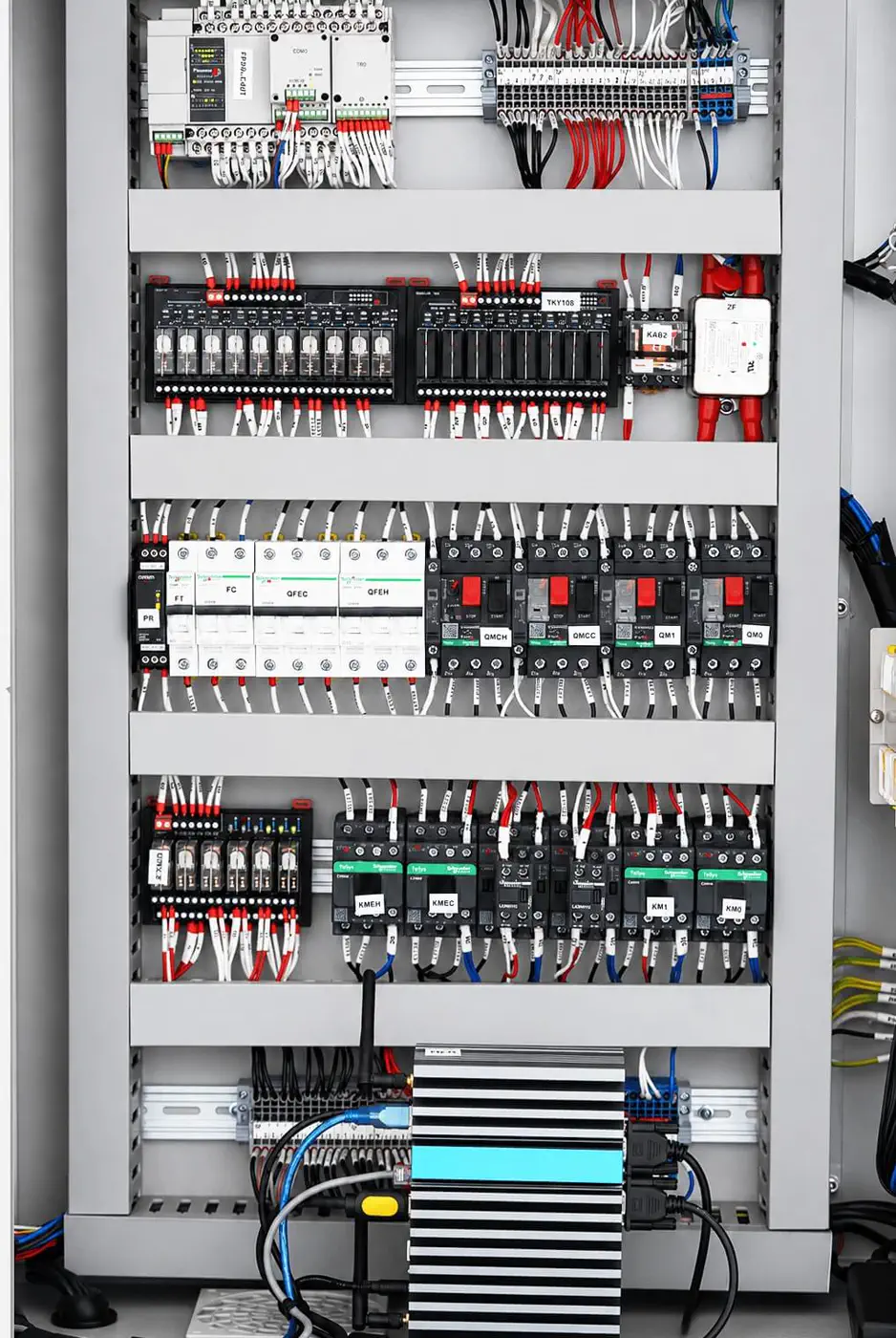
Thermal shock electrical cabinet inspection view
Electrical organization
CLOSED-LOOP QUALITY GATES

Quality is checked at the handoff — not only at the end.

Every process owner checks the work, the next process cross-checks the handoff, and final QA controls release. Identified issues are rectified and re-checked before sign-off.

01 · SELF-CHECKWorkstation owner verifies requirements and workmanship.
02 · CROSS-CHECKNext process validates the upstream handoff.
03 · FINAL QACompleted equipment receives formal release review.
0 unresolved issues permitted at release · rectification and re-check close the loop.
⚡
Electrical & control · 58Installation, wiring, protection, controller communication, actions and alarms.
▣
Structure & appearance · 55Door, seal, basket path, exterior assembly, hardware fit and finish.
❄
Refrigeration · 48Components, piping fabrication, fastening, insulation, sealing and zone checks.
✓
Commissioning & release · 62Programs, specification conformity, transfer tests, labels and sign-off.
Source: supplied SCI factory inspection framework. Final release records follow the approved project scope.
03.10 · REQUEST A SELECTION

Turn the selected basket class into a practical RFQ.

Share the standard, specimen dimensions, fixture, mass, heat load, hot/cold profile, dwell, cycle count, utilities and acceptance basis. The selected family model is carried into the request automatically.

Basket and handling reviewRecovery and acceptance-basis reviewPower, cooling and installation reviewModel-specific specification on request
ENGINEERING CONSULTATION

Turn your requirement into a buildable chamber specification.

Share the essentials. Our application engineers will help define a practical, reliable system.

Application and standards reviewPractical chamber configurationInitial response within 1 business day
SCI INSTRUMENTS CO.LTD
info@scicoolings.com
PROJECT ENQUIRY

Request Engineering Consultation

Tell us the essentials. Our application engineers will help complete the specification.

Quick Chamber Selection
Select your test method, control variables and workspace. SCI will use these inputs to recommend the practical configuration.