
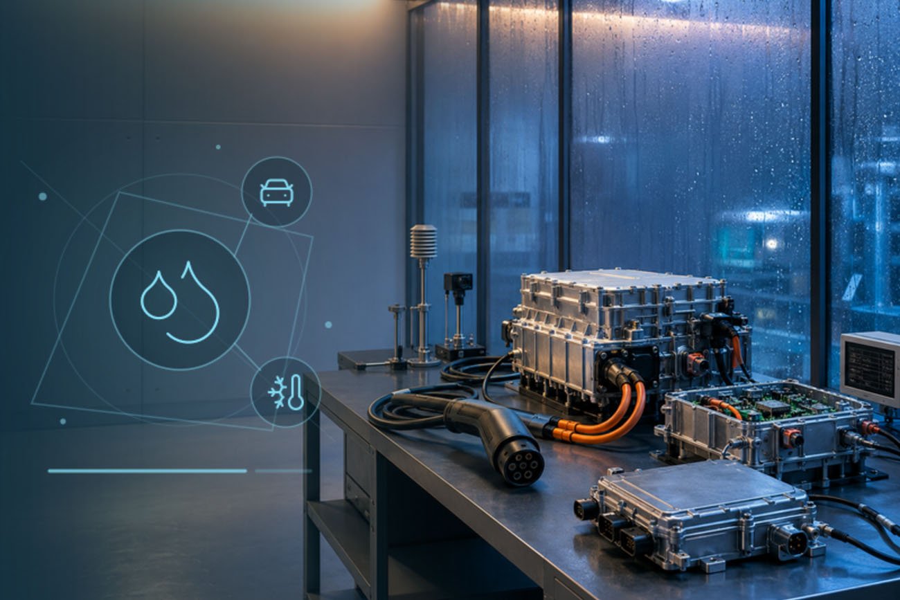
Electric-vehicle components combine high power density, compact packaging and demanding service environments. Inverters, onboard chargers, DC/DC converters, battery-management electronics, sensors and high-voltage connectors may experience cold starts, self-heating, road spray, humid air and rapid transitions between operating states. Those transitions can create both mechanical stress and moisture-related risk.
Temperature cycling and condensation testing should therefore be treated as related but distinct engineering tools. One focuses on repeated expansion and contraction; the other evaluates what happens when surface temperature falls below the local dew point.
Why EV assemblies are vulnerable
An EV power-electronics assembly may contain aluminum housings, copper conductors, ceramic substrates, polymer seals, potting compounds, solder joints and printed circuit boards. Each material responds differently to temperature. Repeated cycling can fatigue bonds, open marginal connections, change contact resistance or create micro-paths for moisture.
Condensation adds another mechanism. Water films can reduce insulation resistance, promote electrochemical migration and accelerate corrosion. A sealed housing may still be affected by pressure changes, permeation, connector interfaces or residual moisture trapped during assembly.
Choose the correct thermal stress
Conventional temperature cycling is suitable when the objective is controlled, repeated expansion and contraction over a specified rate and dwell time. Rapid temperature change increases the stress rate and can reveal weak interfaces sooner, but only when the specimen itself follows the chamber air closely enough. Thermal shock creates a more abrupt transfer and is appropriate for certain components and specifications, but it should not be selected merely because it sounds more severe.
Before testing, define whether ramp rate is measured in empty-chamber air, supply air, workspace air or at the specimen. For high-mass assemblies, product temperature may lag significantly behind the chamber display. Attach independent sensors to representative locations and use product response—not only air temperature—to confirm the intended exposure.
Control condensation intentionally
Condensation is governed by temperature, humidity and dew point. A humidity cycle that never drives the specimen surface below dew point is not a condensation test. Conversely, uncontrolled condensation can create an exposure that is more severe or less repeatable than the approved plan.
A controlled program should define:
- Initial specimen temperature and moisture condition.
- Air temperature and relative-humidity trajectory.
- Target dew-point margin or intended condensation window.
- Powered or unpowered specimen state.
- Electrical safety limits and insulation monitoring.
- Drying or stabilization steps before final measurements.
For energized high-voltage components, risk assessment, current limitation, emergency isolation and external safety monitoring must be designed into the complete test setup. The chamber provides the environment; it does not replace specimen-specific electrical safety controls.
Match the chamber to the heat load
Powered EV components can reject substantial heat. The chamber must remove that load while maintaining the required air and specimen conditions. Cooling capacity, airflow, cable ports, busbar routing, fixture design and external instrumentation all influence the result. Large battery or power-electronics assemblies may require a walk-in chamber or a customized interface panel.
Stable data acquisition is equally important. Synchronize chamber conditions with voltage, current, insulation resistance, communication status and selected temperatures so intermittent events are not lost.
Create repeatable evidence
Automotive climatic testing is often structured around ISO 16750 climatic loads, IEC 60068 methods and customer-specific requirements. The correct test is the approved project profile, including its measurement locations and acceptance criteria.
SCICOOLING supports temperature, humidity, rapid-change, thermal-shock and walk-in configurations for EV components. A successful system is built around the specimen: its mass, power, interfaces, hazards and data—not simply the lowest and highest temperature printed on a chamber specification.
Editorial note: Confirm the contractual standard edition, test severity, acceptance criteria and final internal URLs before publication.